
5 Considerations for the Mechanical Design, Assembly, and Alignment of Optical Systems
To expand on the tips provided in 5 Tips for Designing with Off-the-Shelf Optics, here are some important assembly items to consider when working on an optical design. Typically, optical designers use ray tracing software to construct an optical design, however, the software presents a system that is, essentially, floating in air. When you ultimay purchase and/or manufacture the optical components, you'll need a way to mount, assemble, and possibly align that system. By including considerations for mechanical design, assembly, and alignment in the optical design stages, you can save significant time and reduce the need for costly changes and component redesign later.
1. Consider Package Size and Weight
One of the first things you should consider when planning how to mount optical components is potential size or weight limitations this can drive your overall approach to the mechanical mounting design for the optics. Are you setting up prototype components on a breadboard with an entire table available? Is there a limited amount of space? Is this being carried by a person? These types of considerations may limit the number of possible mounting and/or alignment options. You should also consider where the object, image, and s of your system will be located, and if you need to be able to access them after the final assembly. The s, a fixed-size or adjustable physical aperture that limits the bundle of light that can pass through a system, can be located somewhere within the optical design, or at either end. It is important to ensure that there is enough space where the location of the s is in your optical design so it can be physically achieved in the mechanical design. As shown in Figure 1, the left optical design example is a feasible design, whereas it is unlikely an adjustable iris could be fit between the doublets in the right example. The potential space restriction is an easy fix in the optical design stage, but difficult to fix later on.
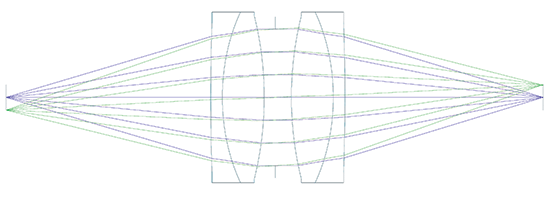
Figure 1: Optical design examples of a 1:1 image relay system requiring an adjustable iris
2. Is it Designed to be Reassembled?
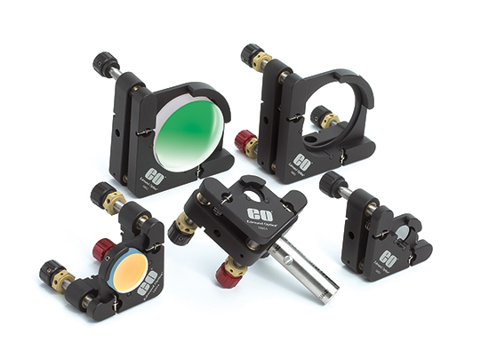
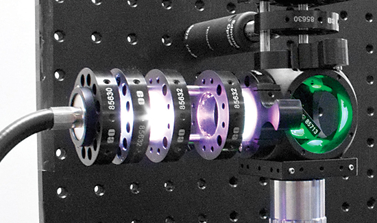
When you are planning the assembly process for your optical design, one detail that can drive design decisions is whether or not the assembly is one-time only or if it will be disassembled and reassembled. If there is no need to disassembly, then using adhesives or other permanent/semi-permanent mounting methods may not be a problem. However, if you need to disassemble or modify the system, consider in advance how this will be done. If you are swapping out parts, such as rotating different coated mirrors in and out of the same setup, determine if you will be able to access those components easily and if you need to maintain the alignment of the component. This is where kinematic mounting options or the TECHSPEC® Optical Cage System, such as those shown in Figure 2, can save you a lot of time and frustration.
3. Understand Motion and Alignment Requirements
For some simple systems, optical components can simply be placed in their holders or a barrel and the assembly and alignment is complete without need for adjustments. However, in many cases, optical components must be aligned properly and possibly adjusted during use to maintain the required design performance. When creating an optical design, consider if you will need adjustments for decenter (translation in X and Y), axial motion (translation in Z), angular motion (tip/tilt), and in the case of components such as polarizers, waveplates, or diffraction gratings, orientation. Such adjustments may be required for individual components, the light source, the camera/image plane, or the entire system. Not only is it important to know what adjustment, the more expensive the mechanics will be and more skill we be required from the assembler. Understanding the motion requirements can save time and money.
4. Avoid Stray Light
Stray light is a general term that applies to any unwanted light in an optical system. Light traveling where it was not intended in the optical design can cause a variety of issues including ghost (multiple) images, reduced image contrast, or even glass failures in the case of high power laser applications. Standard ray tracing software packages typically have some level of first order stray light analysis that can be used to evaluate if this is a potential concern for your optical system. More thorough investigations can also be completed using a non-sequential ray trace analysis. Figure 3 shows a stray light analysis completed in FRED (optical design software) to investigate the effects of light reflecting off a particular metal surface.
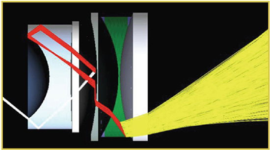
Figure 3: Stray Light Analysis can help Avoid Image Contrast Problems in the Final Design
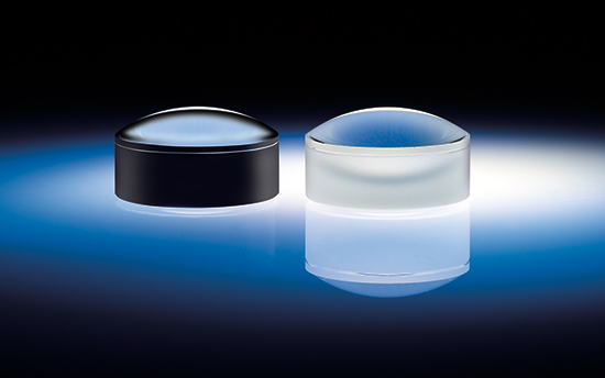
If stray light is a potential problem for your optical system, there are a few approaches to mitigate the effects. For example, threading the inner diameters of barrels or placing additional apertures to block stray light from exiting the system can be used to block unwanted rays. Additionally, mounting components can be blackened (i.e. black anodized for aluminum or black oxide for steels) or covered with material. The edges or lenses can also be blackened with paint or ink, as shown in Figure 4. Ideally, any stray light problems should be recognized during the design phase and the elements or image plane can be moved or modified to resolve the issue.
5. Watch Out For Environmental Effects
As mentioned earlier, when designing an optical system using modeling software, it is typically floating in air with no environmental effects acting upon it. In reality, however, the optical system may see many adverse environmental conditions including stress, acceleration/shock (if it is dropped), vibration (during shipment or operation), temperature fluctuations, or it may need to operate underwater or in another substance. If you anticipate your optical system will not be operating in air under controlled conditions, further analysis should be completed to either minimize the environmental effects through the design (passive solution) or having an active feedback loop to maintain the performance of the system. Most optical design programs can stimulate some of these aspects, such as temperature and pressure, but additional programs might be required for a complete environmental analysis.
版權所有 © 2026 江陰韻翔光電技術有限公司 備案號:蘇ICP備16003332號-1 技術支持:化工儀器網 管理登陸 GoogleSitemap


